- Home
- PRODUCT CENTER
- ABOUT US
- BLOG
- Application
- FAQ
- CATALOGUE
- Contact Us
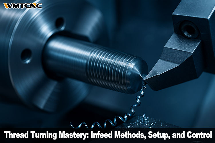
Thread turning looks familiar—carriage motion, rotating work, indexable inserts—but it is not ordinary turning. In standard turning, you can dial cutting speed, feed, and depth of cut independently. In threading, the feed rate must match the thread lead exactly, and you almost always reach full depth via multiple passes to protect the insert’s delicate nose radius. These constraints demand meticulous planning of infeed strategy, chip control, and safe entry/exit—especially on CNC lathes where feed-rate ceilings, inertia, and collision risks must be respected.

Thread turning produces helical grooves (external or internal) with a lathe while the tool tracks the helix at a feed equal to the pitch. External threading is generally simpler: you have space for chips, better visibility, stiffer tools. Internal threading raises the stakes: longer, slender bars, blind holes, tighter evacuation windows, and higher vibration risk. Good practice divides the total depth into a planned series of cuts so the insert tip isn’t overloaded.
The non-negotiable rule is feed = pitch. On CNC, this is enforced by the control when you program threading cycles; on manuals, it’s enforced by the spindle-to-lead-screw ratio and half-nut engagement. Coarse pitches on small diameters stress the machine: surface speed spikes quickly; feed becomes large per rev; acceleration and deceleration windows tighten. Plan pass schedules and safe retracts so you never “outrun” the machine.

Thread hand arises from spindle direction and tool feed direction. Choose tool orientation to support the dominant cutting forces—e.g., right-hand tool for right-hand thread in external work. For internal threads, consider pull threading (left-hand tool for right-hand thread) to pull chips toward the bore entry; just secure the insert to control movement under tensile load.
Long stick-out and slender components invite chatter. Keep overhang minimal, choose stiffer bars (carbide or damped), use steady/follow rests for long shafts, and match nose radius to the pitch and material. Align the tool on center; even a small height error degrades flank contact and finish.

External threading benefits from open chip flow and stronger toolholders. Focus on:
Feed equals pitch (always).
Select the number of passes and depth schedule to distribute heat.
Prevent chip wrapping; tune chipbreaker and infeed to avoid “bird-nesting.”
Manage vibration in slender work (steady rest, tailstock, or center).
Internal threads are more demanding:
Favor modified flank infeed to generate a spiral chip that exits the bore.
Use air blast or high-pressure coolant to clear chips, especially in blind holes.
Shorten overhang; if reach is unavoidable, use carbide/damped bars.
Align carefully; re-measure center height and verify insert tightness before the first pass.

Add a 30° chamfer that is slightly deeper than thread depth. This guides the tool into the cut, protects the vulnerable insert tip, and prevents crest damage on first contact. Provide a thread relief/undercut for a clean exit; confirm that your retract path clears shoulders, chucks, and live centers.
Plan passes to reach full thread height without overheating the nose. For the first article, cut a scratch pass and verify pitch with wires or a gauge. On manual lathes, respect thread dial marks (or keep half-nuts engaged for metric threads). On CNC, check cycle parameters and safe retract vectors with a high-clearance dry run.

Choose insert grade/coating for the work material. A really sharp edge is tempting, but a light edge hone may stabilize the cut and extend life in gummy steels. Match chipbreaker to your infeed style—spiral chips are your friend in bores; avoid long stringers that tangle on the holder.
Use directed coolant or an air blast to shepherd chips away from engagement, especially in internal and blind threads. In tough alloys, a steady, cool cut improves flank integrity and preserves geometry.
| Infeed Method | How It Cuts | Pros | Cons | Best Use Cases |
|---|---|---|---|---|
| Radial | Straight into the V; both flanks cut | Simple to program; easy to visualize | Heat at tip; shorter tool life; chip wrapping risk | Easy materials; external threads; shallow depths |
| Flank | Bias to one flank at angle | Better chip control & heat flow | Non-cutting flank finish can suffer | Tougher alloys; controlled chip flow |
| Modified Flank | Flank-biased with trailing-edge relief | Extends tool life; better finish; spiral chip | Slightly more complex to set | Internal threads; blind holes; finish-critical work |
| Alternating Flank | Alternates cutting flank per pass | Balances wear across nose | Chip control can be harder | Long runs needing symmetric wear |

Thread turning rewards forethought. Respect the non-negotiables—feed = pitch, planned pass schedules, and safe exits. Pick an infeed strategy that matches your material, geometry, and evacuation realities. Prepare your chamfer and relief, keep tools aligned and supported, and validate with a scratch pass before committing. On CNC, trust cycles but verify retracts; on manual lathes, trust the dial but verify the math. With disciplined setup and pragmatic troubleshooting, you’ll hold pitch, nail flank finish, and deliver threads that gauge right—first time and every time.
DC motors offer precise speed and high starting torque for robotics and EVs but need maintenance. AC motors are rugged, low-cost, with long lifespan—ideal for HVAC, industrial machinery, and appliances.>> Read more
CNC automation leverages digital control to streamline machining for precision, speed, and cost-efficiency. By replacing manual input with CAD/CAM-driven G-code, modern CNC systems drive consistent, high-volume production.>> Read more
Shaper machines utilize a reciprocating single-point cutter to shape flat surfaces, grooves, and profiles. Available in crank, hydraulic, vertical, universal, and traveling-head types, they excel in heavy-duty, precise, short-run tasks and are increasingly adapted with CNC retrofits.>> Read more
Before starting a CNC machine, inspect for electrical issues, oil leaks, and environmental hazards. Ensure proper lubrication, tool alignment, and safety checks to maintain optimal performance.>> Read more
CNC lathe machines offer high-precision, automated turning for complex parts, enabling efficient, flexible production. They support multi-material machining, reduce setup time, and enable real-time monitoring and tool wear compensation.>> Read more


Tags: Thread Turning, Turning